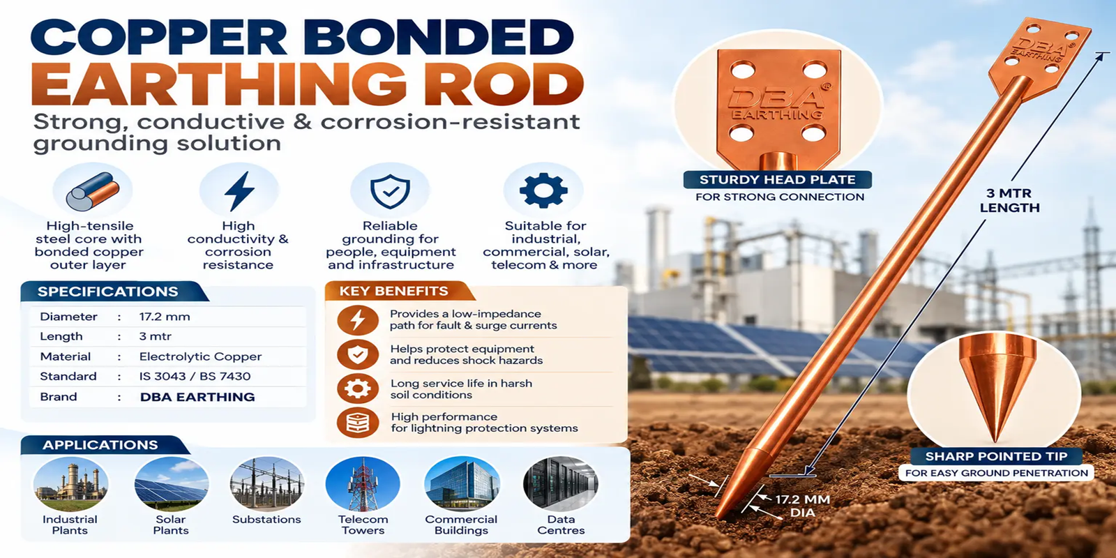
A copper bonded earthing rod is a high-performance grounding solution designed to safely discharge fault current, leakage current, and lightning-induced surges into the earth. With a high-tensile steel core and a molecularly bonded copper outer layer, it offers the mechanical strength needed for deep installation along with the conductivity and corrosion resistance needed for long-term electrical safety.
For industrial facilities, solar plants, substations, telecom towers, commercial buildings, data centres, and critical electrical infrastructure, choosing the right earthing Rod is essential.
What Is a Copper Bonded Earthing Rod?
A copper bonded rod—also called a copper bonded earth rod, copper clad earth rod, copper bonded grounding rod, or copper coated steel rod—is a vertical grounding conductor driven into the soil.
It typically consists of:
- A high-tensile, low-carbon steel core
- A thick outer coating of high-purity copper
- Threaded or non-threaded ends, depending on the installation method
- Compatible accessories such as couplers, driving heads, clamps, inspection chambers, and earthing strips
The steel core makes the rod strong enough to withstand driving forces during installation. The copper layer improves electrical conductivity and provides greater resistance to corrosion compared with many conventional grounding materials.
The Rod creates a low-impedance path for fault and surge currents to dissipate safely into the earth, helping protect people, machinery, electrical panels, automation systems, and connected equipment.
Why Copper Bonded Earthing Rods Matter
An effective earthing system is not simply an installation requirement—it is a safety system. During insulation failure, short circuits, transient surges, or lightning events, excess current must move safely into the ground rather than passing through equipment or exposed metal surfaces.
Copper bonded earthing Rods help achieve this by providing:
- A reliable path for fault current to reach the soil
- Improved protection against electrical shock hazards
- Reduced risk of damage to motors, drives, PLCs, UPS systems, inverters, and sensitive electronics
- Better grounding performance for lightning protection systems
- Strong corrosion resistance in humid, saline, acidic, alkaline, and industrial soil conditions
- Long service life when the product is selected and installed correctly
Copper-coated steel earth rods are recognised in lightning-protection Rod requirements; IEC 62561-2 covers requirements and tests for metallic earth Rods, including copper-coated steel rods.vde-verlag+1
Copper Bonded Earthing Rod Types
Copper bonded Rods are available in multiple configurations. The right type depends on soil resistivity, expected fault current, site access, installation depth, and the earthing design prepared by a qualified electrical engineer.
| Type | Construction | Best-suited applications |
| Copper bonded earth rod | Copper-bonded steel rod driven vertically into the ground | General industrial, commercial, solar, telecom and building earthing |
| Threaded copper bonded rod | Rod with threaded ends for couplers and extensions | Deep earthing in high-resistivity soil or projects needing multiple rod sections |
| Pointed copper bonded rod | Rod with a pointed driving end | Faster penetration in normal soil conditions |
| Flat-end copper bonded rod | Rod with a flat top for driving-head use | Controlled installations using a hammer or mechanical driver |
| Copper bonded earth Rod with inspection chamber | Rod installation with test link and chamber | Sites requiring easy periodic testing and maintenance access |
| Copper bonded rod with earth enhancement compound | Rod surrounded by conductive backfill compound | Dry, rocky, sandy, or high-resistivity soil areas |
| Copper bonded earthing grid system | Multiple rods interconnected through strips or conductors | Substations, solar plants, data centres, industrial plants and large electrical networks |
For high-resistivity soil, one rod may not be sufficient. The design may require deeper rods, multiple parallel Rods, an earthing grid, conductive enhancement material, or a combination of these solutions.
Copper Bonded Rod Specifications
Before buying a copper bonded earthing rod, assess technical specifications rather than selecting only on price. The rod’s construction, copper thickness, length, diameter, connection method, and testing provisions directly affect durability and earthing performance.
| Specification | Typical requirement | Why it matters |
| Core material | High-tensile low-carbon steel | Provides strength during driving and deep installation |
| Outer layer | High-purity copper molecularly bonded to steel | Improves conductivity and corrosion resistance |
| Copper bonding thickness | Often specified around 250 microns for demanding projects | A thicker, uniform layer generally improves corrosion resistance and expected service life |
| Rod diameter | Common sizes include 14.2 mm, 17.2 mm, 20 mm and 25 mm | Larger diameters offer greater mechanical strength and surface area |
| Rod length | Commonly 1 m, 1.5 m, 2 m, 3 m or coupled lengths | Longer/deeper Rods can reach lower-resistivity soil layers |
| Tensile strength | Should suit driving and site conditions | Prevents bending, breakage, or deformation during installation |
| End configuration | Threaded, non-threaded, pointed, or flat-end | Determines compatibility with couplers and driving accessories |
| Connection system | Tested clamp, bimetallic connector, or exothermic weld | Ensures durable electrical continuity between the conductor and Rod |
| Test facility | Inspection pit, test link or earth chamber | Enables periodic earth-resistance testing and visual inspection |
A specification used in some Indian public procurement documents calls for high-tensile low-carbon steel rods molecularly bonded with copper, with examples of 17 mm diameter, 3 m length, and 250-micron copper bonding for designated applications. Actual requirements must always follow the project’s approved earthing design, fault level, soil survey, and contract specification.
Copper bonding process
A genuine copper bonded Rod should not be confused with a lightly copper-plated rod. In a quality copper bonded earth rod, the copper coating is metallurgically or molecularly bonded to the steel core to reduce the risk of peeling, cracking, or separation during driving.
When comparing products, ask the supplier for:
- Copper bonding thickness test details
- Core material and tensile-strength information
- Product dimensions and tolerances
- Applicable test reports or compliance documentation
- Details of clamps, couplers, driving heads, and connection accessories
- Guidance on installation for your soil type and electrical load
Copper Bonded Earthing Rods vs GI Earthing Rod
Both copper bonded and GI earthing Rods can be used in earthing systems, but they are selected for different technical and budget requirements.
| Factor | Copper bonded earthing Rod | GI earthing Rod |
| Core construction | Steel core with bonded copper outer layer | Iron or steel protected with zinc galvanisation |
| Conductivity | High, because copper is highly conductive | Lower than copper-based solutions |
| Corrosion resistance | Strong performance in many aggressive soil conditions | Zinc coating may deteriorate over time in corrosive environments |
| Mechanical strength | High, due to the steel core | High, depending on rod/pipe construction |
| Initial investment | Usually higher | Usually lower |
| Lifecycle value | Often favourable for critical, long-life installations | Can suit standard or budget-sensitive projects |
| Suitable projects | Substations, solar plants, data centres, telecom, industrial plants, lightning protection | Residential, small commercial and less demanding installations, subject to design |
| Maintenance need | Can be lower when correctly installed | May need closer monitoring in corrosive soil |
A copper bonded rod is often preferred where corrosion risk, high fault-current duty, difficult maintenance access, long project life, or critical uptime make long-term reliability more important than initial cost.
How To Select The Right Earthing Rod
There is no universal “best” rod size or resistance value for every project. Selection should be based on the earthing design, not a generic product claim.
Consider the following before choosing a copper bonded earthing Rod:
- Soil resistivity: High-resistivity, dry, rocky, sandy, or filled soil may require deeper rods, multiple Rods, or earth enhancement material.
- Soil chemistry: Saline, acidic, alkaline, moisture-rich, and industrial-contaminated soil can accelerate corrosion.
- Fault-current level: Substations, industrial panels, transformer yards, and high-capacity systems may need a designed earthing grid rather than a single Rod.
- Application criticality: Data centres, telecom infrastructure, solar inverters, hospitals, process plants, and control systems require stable, dependable grounding.
- Available installation depth: Where deep vertical driving is difficult, a grid, multiple shorter Rods, or alternative grounding geometry may be more suitable.
- Lightning-protection requirement: Lightning earth systems require appropriate Rod layout, bonding, down-conductor connection, and surge-protection coordination.
- Testing access: An inspection chamber and test link should be included where regular testing is required.
- Applicable standards and drawings: Follow the approved electrical design, local regulations, client specification, and relevant standards such as IS 3043 principles for earthing design.
IS 3043 guidance emphasises practical testing and earth-resistance measurement procedures, while IEEE 81 covers methods for measuring earth resistivity, grounding-system resistance or impedance, and surface potentials.
Copper Bonded Earthing Rod Installation
Correct installation is as important as product quality. A high-quality Rod can still perform poorly if it is placed in unsuitable soil, connected with poor-quality clamps, or installed without testing.
1. Conduct a site survey
Start with a soil-resistivity survey and site assessment. Identify:
- Soil type and moisture condition
- Rock layers, underground utilities, pipelines, and foundations
- Corrosive soil conditions
- Available Rod depth
- Distance from electrical equipment and structures
- Required earth-resistance target according to the project design
The final resistance target should be defined by the system design and safety study—not simply by a generic rule. Requirements can differ significantly between a residence, commercial building, telecom site, solar plant, generator installation, and substation.
2. Select the installation location
Choose a location that is accessible for testing, protected from mechanical damage, and away from areas likely to be disturbed by excavation or construction activity.
Avoid placing earthing Rods where they may be affected by:
- Future foundation work
- Heavy vehicle movement
- Continuous waterlogging without design consideration
- Chemical discharge zones
- Underground gas, water, communication, or power lines
3. Prepare the Earthing Rod and accessories
Ensure the required components are available before work begins:
- Copper bonded earth rod
- Coupler, if multiple rod sections are required
- Driving head to protect threaded ends
- Earth clamp or exothermic welding materials
- Copper strip, GI strip, copper conductor, or approved grounding conductor
- Earth enhancement material, if specified
- Inspection chamber or earth pit cover
- Earth-resistance tester
Do not hammer directly on threaded rod ends without a driving head. Damaged threads can prevent correct coupling and may weaken the installation.
4. Drive the Earthing Rod vertically
Drive the rod vertically using a suitable manual or mechanical method. Maintain alignment as much as possible to avoid bending or damaging the copper-bonded coating.
Where deeper installation is required:
- Attach the next rod section with an approved coupler
- Ensure threads are properly engaged
- Use the recommended driving head
- Continue driving without exposing or damaging the connection
- Keep the final accessible connection inside an inspection chamber where required
For difficult soil or rocky strata, do not force a rod if it risks bending or damaging the copper layer. Review the design and consider a different location, a pre-drilled installation method where approved, multiple Rods, or an earthing grid.
5. Use earth enhancement material if specified
In dry, sandy, rocky, or high-resistivity soil, the Rod may be installed with a conductive earth enhancement material. This helps improve soil contact and stabilise the electrical environment around the Rod.
Use only approved materials according to the project specification. Avoid relying on traditional salt-and-charcoal treatment as a substitute for an engineered earthing design. Salt can be corrosive, can leach away, and may produce unstable long-term results.
6. Make a secure conductor connection
Connect the earth conductor to the Rod using an approved mechanical clamp, bimetallic connector, or exothermic weld.
A good connection should be:
- Electrically continuous
- Mechanically secure
- Suitable for the conductor and Rod materials
- Protected against corrosion
- Accessible for inspection where required
- Sized according to the fault-current and earthing design
For high-reliability systems, exothermic welding is commonly selected because it creates a permanent molecular connection. However, the right method depends on the project specification and the materials being joined.
7. Install an inspection chamber
Install an inspection pit or chamber around the Rod connection point where periodic inspection and testing are required. The chamber should protect the joint while allowing access to the test link and conductor connection.
Clearly mark earthing locations on as-built drawings for future maintenance teams.
How To Test A Copper Bonded Earthing Rod
Testing confirms whether the installed earthing system performs as designed. Visual inspection alone cannot determine whether an earth Rod has acceptable resistance or whether a connection has deteriorated.
Earth resistance testing methods
Common methods include:
| Test method | Best use | Key point |
| Fall-of-potential test | Individual Rod, larger grounding systems and commissioning verification | Measures resistance by injecting current and measuring voltage at varied probe distances |
| Three-point earth test | Single Rods and smaller installations | Common field method using an earth tester and auxiliary test probes |
| Four-point soil resistivity test | Pre-installation site assessment | Used to assess soil resistivity and support earthing-system design |
| Clamp-on earth test | Interconnected grounding systems where a return path exists | Useful for maintenance checks but not suitable for every isolated Rod setup |
| Continuity test | Earth conductor, bonds, joints, and connections | Confirms electrical continuity but does not replace earth-resistance testing |
IEEE 81 describes methods for measuring earth resistivity, grounding-system resistance or impedance, touch and step voltages, and factors that can distort measurements.
Basic fall-of-potential test process
The fall-of-potential method is widely used for reliable earth-resistance measurement. In simple terms, the tester injects a known current through the earth and measures voltage at different locations. The resistance is calculated from R=V/IR = V/IR=V/I.
A typical process includes:
- Isolate the Rod under test where the test method and safety procedure require it.
- Connect the earth tester to the Rod, potential probe, and current probe.
- Place auxiliary probes in a straight line at suitable distances as directed by the tester manufacturer and test procedure.
- Take readings at several potential-probe positions.
- Check for a stable portion of the resistance curve rather than relying on one reading alone.
- Record test conditions, weather, soil condition, date, location, instrument details, and measured results.
- Compare results with the approved project target and take corrective action if necessary.
IS 3043 describes procedures involving test Rods and repeated readings to identify a stable resistance value, while fall-of-potential testing is also recognised in IEEE grounding measurement guidance.
Important testing note
Do not claim a fixed value such as “below 1 ohm” or “below 5 ohms” for every site without an electrical design basis. Acceptable resistance depends on the installation type, fault level, earthing grid arrangement, utility requirements, equipment sensitivity, and applicable project specification.
If resistance is higher than the approved target, possible corrective actions may include:
- Installing additional Rods in parallel
- Increasing Rod depth
- Increasing spacing between Rods
- Adding approved earth enhancement material
- Extending the grounding grid
- Improving conductor connections and bonding
- Revisiting the site’s soil-resistivity data and grounding design
Key Applications
Copper bonded earthing Rods are used wherever safety, uptime, and long-term grounding reliability are important.
Solar power plants
Solar PV plants contain sensitive inverters, DC combiner boxes, modules, AC panels, transformers, and communication equipment. A properly designed earthing system for solar power plants helps protect against fault currents, insulation failure, lightning-related surges, and equipment damage.
For utility-scale solar plants, Rod networks are commonly integrated with an earthing grid rather than relying on one isolated rod.
Electrical substations
Substations require engineered grounding systems that can manage high fault currents and control touch and step potentials. Copper bonded rods may be used as part of a broader earthing grid, particularly where deep vertical Rods are needed to access lower-resistivity soil.
Industrial plants
Manufacturing units, process plants, CNC machinery, automation systems, compressors, boilers, motors, VFDs, and control panels need effective grounding for personnel safety and equipment protection.
Data centres and IT facilities
Servers, networking devices, UPS systems, precision cooling equipment, and communication hardware are sensitive to voltage disturbances. Proper earthing and bonding help reduce electrical-noise and surge-related risks.
Telecom towers and communication networks
Telecom towers, antenna systems, radio equipment, shelters, and communication cabinets require robust earthing and lightning-protection arrangements. Copper bonded Rods are frequently selected for their conductivity and corrosion resistance.
Commercial and residential buildings
Commercial buildings, apartments, schools, hospitals, hotels, shopping facilities, and homes all need safe grounding for electrical panels, appliances, generators, lifts, HVAC systems, and lightning protection systems.
Railway, infrastructure and utility projects
Railway signalling, infrastructure networks, utility distribution systems, outdoor cabinets, pumping stations, and street-lighting networks may require corrosion-resistant grounding solutions designed for demanding field conditions.
Advantages Of Copper Bonded Earthing Rods
Copper bonded Rods provide a practical balance of performance and cost.
- High conductivity: The copper surface supports efficient dissipation of electrical fault and surge currents
- Mechanical durability: The steel core helps withstand installation force and deep driving
- Corrosion resistance: The copper layer offers better protection in many aggressive soil environments
- Long service life: Proper product selection and installation can reduce premature replacement requirements
- Cost efficiency: They can provide many benefits of copper while using a steel core instead of solid copper throughout
- Deep installation capability: Threaded versions can be extended with couplers to reach more conductive soil layers
- Versatility: Suitable for industrial, commercial, renewable-energy, telecom, and residential applications
- Compatibility: Can be integrated with earthing strips, copper conductors, test links, inspection pits, lightning-protection systems, and earth enhancement materials
Common Installation Mistakes To Avoid
Avoiding these issues can significantly improve grounding performance and product life:
- Selecting rod size without a soil-resistivity study or approved design
- Installing a single rod and assuming it will meet every project’s target resistance
- Using lightly plated or poorly bonded rods instead of genuine copper bonded Rods
- Hammering directly on threaded ends and damaging the threads
- Using undersized, loose, or incompatible clamps
- Allowing dissimilar-metal connections without suitable bimetallic protection
- Failing to provide an inspection pit or test point
- Locating rods too close together, which can reduce the effectiveness of parallel Rods
- Ignoring corrosion risks in saline, chemical, coastal, or industrial soil
- Skipping commissioning tests and periodic maintenance
- Using salt as a long-term substitute for an engineered earthing solution
Choose The Right Earthing Solution With DBA Earthing
A copper bonded earthing rod performs best when it is part of a complete earthing solution—not just a standalone product. The final system should account for soil resistivity, corrosion risk, electrical load, fault current, lightning exposure, equipment sensitivity, and future maintenance access.
As a trusted earthing materials manufacturer and supplier, DBA Earthing helps customers select suitable earthing Rod, strips, clamps, couplers, inspection chambers, lightning-protection components, and installation solutions for residential, commercial, industrial, solar, telecom, and infrastructure projects.
For a reliable copper bonded earthing system, share your project details, location, soil condition, application type, and required quantity. Our team can help you choose an appropriate solution for safe, durable, and cost-effective grounding.