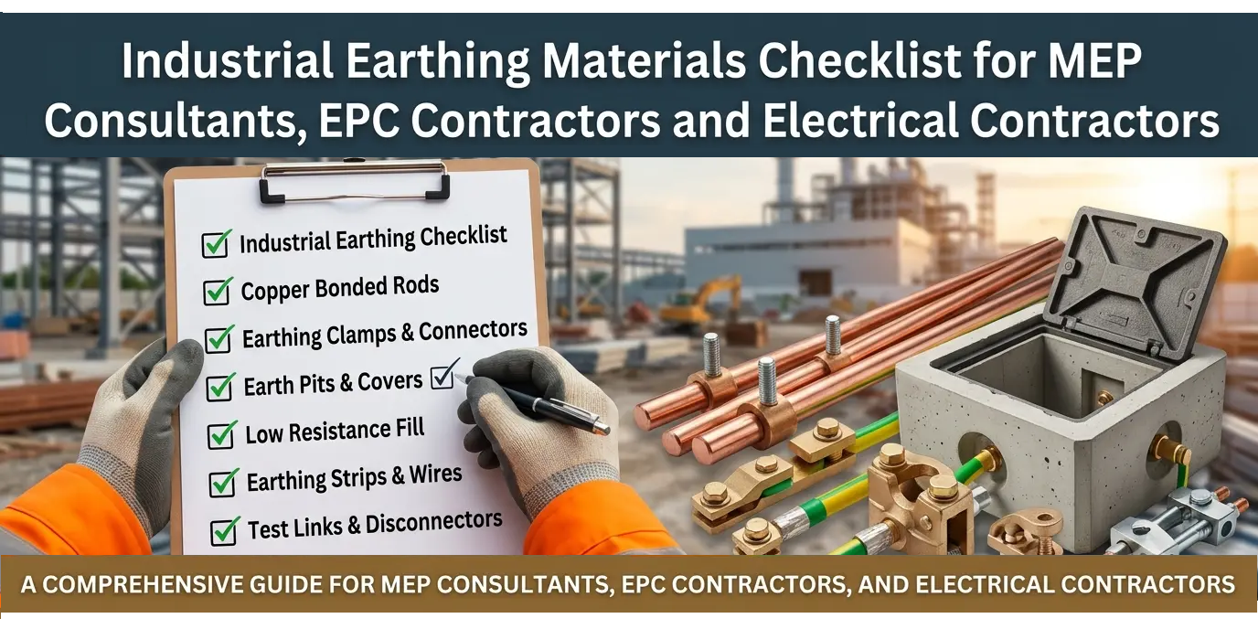
A reliable industrial earthing system protects people, equipment, and continuity of operations. For MEP consultants, EPC contractors, and electrical contractors, the biggest risk is not choosing one earthing electrode—it is missing a small but critical material, accessory, or testing requirement during procurement and installation.
This checklist helps you plan an industrial earthing package systematically: from soil study and electrode selection to conductors, pits, bonding, testing, and handover documentation.
Why Industrial Earthing Needs a Complete Checklist
Industrial projects have higher fault levels, more metallic structures, sensitive equipment, and stricter safety expectations than small residential installations. A complete earthing system must provide a low-impedance path for fault current, remain stable over time, resist corrosion, and allow periodic testing.
For an MEP consultant, the checklist supports accurate specifications and BOQ preparation. For an EPC contractor, it reduces scope gaps and site rework. For an electrical contractor, it ensures that materials installed at site match the approved design and testing requirements.
Pre-Procurement Checklist
Before finalising earthing materials, confirm the following project inputs:
- Soil resistivity report and soil condition: rocky, sandy, clayey, dry, coastal, or chemically aggressive.
- Expected fault current, clearing time, and system voltage.
- Type of installation: factory, substation, plant room, solar plant, data centre, warehouse, or industrial shed.
- Number of earthing pits and proposed electrode layout.
- Requirement for equipotential bonding of panels, cable trays, structures, tanks, and equipment.
- Lightning protection requirements, if applicable.
- Approved single-line diagram, earthing layout, and technical specifications.
- Target earth resistance value and testing method.
- Maintenance expectations: conventional earthing or low-maintenance chemical earthing.
Soil resistivity, moisture variation, and expected fault current directly affect electrode type, conductor size, backfill material, and the need for an earth grid or multiple electrodes.
Earth Electrode Checklist
The earth electrode is the main component that dissipates fault current into the ground. Select it based on soil condition, available space, fault level, corrosion risk, and project life.
| Material / System | Best Use | Key Checks |
| Copper bonded rod | Industrial plants, commercial buildings, solar plants, equipment earthing | Copper bonding thickness, rod diameter, length, tensile strength, corrosion resistance, connection clamp compatibility. |
| GI pipe electrode | General industrial and building earthing where cost-effective performance is required | GI class, pipe diameter, length, galvanisation quality, welded flange/connection detail. |
| Copper plate electrode | Locations requiring higher conductivity and long service life | Plate size, thickness, purity, terminal arrangement, pit depth, backfill quality. |
| GI plate electrode | Cost-sensitive installations with suitable soil conditions | Plate dimensions, galvanisation, connection lug, protection against corrosion. |
| Chemical earthing electrode | High-resistivity soil, limited space, dry locations, critical equipment | Electrode material, chemical backfill compound, maintenance-free claim, installation depth, test link provision. |
| Earth grid / multiple electrodes | Substations, large plants, high fault-current areas | Electrode spacing, interconnection conductor, step and touch voltage control, soil conditions. |
For most industrial projects, copper bonded rods are preferred where conductivity, corrosion resistance, and long-term reliability are important. DBA Earthing provides copper bonded rods for grounding systems that safely dissipate fault currents into the earth.
Check before purchase:
- Electrode diameter and length match the approved drawing.
- Material certificate and test report are available.
- Copper bonding is uniform and mechanically durable.
- Electrode is suitable for the site’s soil and corrosion conditions.
- Connection point allows secure conductor termination.
- Quantity includes spare electrodes, if specified.
Earthing Conductor Checklist
Conductors connect equipment, panels, structures, and electrodes. Their size must be based on fault-current capacity, not just convenience or standard practice.
Common conductor options include:
- Copper strip
- Copper wire or cable
- GI strip
- GI wire
- Copper-bonded conductor
- Flexible bonding conductor for equipment connections
Check the following before ordering:
- Conductor material matches the electrode and earthing bar specification.
- Strip width and thickness are suitable for the calculated fault current.
- Copper conductors are used where corrosion resistance and conductivity are critical.
- GI conductors are protected from damage and compatible with the surrounding environment.
- Dissimilar-metal joints are avoided or properly treated to reduce galvanic corrosion.
- Conductors are routed safely, protected where exposed, and accessible for inspection.
Earthing strips and busbars must be sized to carry the prospective fault current for the required clearing time without overheating. Also avoid incompatible metal combinations in damp joints, as this can accelerate corrosion.
Earthing Pit and Backfill Checklist
The earth pit protects the electrode connection and allows future testing. A poorly executed pit can undo the benefit of a good electrode.
Include these items in your BOQ:
- Earthing electrode
- Backfill compound or approved soil-enhancing material
- Earth pit chamber
- PVC, FRP, concrete, or CI pit cover
- Earth pit name plate or identification tag
- Test link or testing terminal
- Connection clamp or lug
- Protective pipe or conduit for conductor, where required
- Masonry or chamber material, if applicable
- Backfill soil and compaction material
For chemical earthing, confirm that the backfill compound is compatible with the electrode and installed as per the manufacturer’s method. Bentonite, conductive compounds, and other backfill materials are commonly used to improve soil contact and maintain stable earth resistance.
Site checklist:
- Pit location is accessible for future maintenance.
- Pit is not in a waterlogging-prone area, unless specially designed.
- Electrode is installed at the specified depth.
- Backfill is placed correctly around the electrode.
- Pit cover is load-rated for the location.
- Test link is visible and accessible.
- Pit is numbered and marked for the earthing schedule.
Earthing Bar, Bonding and Accessories Checklist
Industrial earthing is incomplete without proper bonding. All exposed conductive parts that could become live during a fault should be connected to the earthing system.
Include the following accessories:
- Main earthing bar or earth busbar
- Equalizer or interconnecting earth bar
- Copper or GI strips
- Cable lugs and compression connectors
- Bolted clamps
- U-bolts and rod-to-tape clamps
- Test links
- Exothermic welding kit, where specified
- Anti-corrosion compound or joint protection
- Cable trays bonding continuity connectors
- Equipment earthing terminals
- Structure bonding connectors
- Lightning protection down-conductor connectors, where applicable
Every earthing system should include a test link so resistance can be measured throughout the system’s life. Connections must be tight, accessible, corrosion-protected, and capable of carrying the expected fault current.
Lightning Protection Materials Checklist
If the project includes lightning protection, coordinate the earthing package with the external lightning protection system.
Check for:
- Air termination network
- Down conductors
- Test joints
- Earthing electrodes for lightning protection
- Connection clamps and conductors
- Earth pit for lightning protection system
- Surge protection device coordination, where applicable
- Separation distance or bonding requirements as per design
The lightning protection system should be integrated with the overall earthing design, not treated as a separate site activity. EPC electrical scopes commonly include earth electrodes, earthing conductors and strips, earth pits, covers, equipotential bonding materials, and lightning-protection components.
Installation Checklist for Site Teams
Use this checklist during execution:
- Verify approved earthing layout, BOQ, and technical specifications.
- Conduct or review the soil resistivity test.
- Confirm electrode locations against underground utilities and civil drawings.
- Excavate pits to the specified size and depth.
- Inspect electrodes, strips, clamps, and backfill material before installation.
- Install electrodes vertically and securely.
- Connect conductors using approved clamps, lugs, or exothermic welding.
- Apply corrosion protection at exposed joints.
- Install earth pits, covers, and identification plates.
- Provide test links at accessible locations.
- Connect panels, equipment, cable trays, structures, and metallic enclosures as per the bonding layout.
- Avoid sharp bends, loose connections, and unprotected conductor runs.
- Measure earth resistance after installation.
- Record readings, photos, material details, and test results.
- Obtain consultant or client sign-off before backfilling, where required.
Materials used in earthing systems should withstand mechanical damage, resist corrosion, provide a low-impedance path to earth, and carry the maximum fault condition for the installation.
Testing and Handover Checklist
Do not close the earthing package only after installation. Testing and documentation are equally important.
Before handover, prepare:
- Earth resistance test report for each pit
- Soil resistivity test report
- Continuity test report for bonding conductors
- Material test certificates
- Manufacturer datasheets
- Approved earthing layout drawing
- As-built earthing layout
- Photographs of pits, electrodes, connections, and test links
- Earthing schedule with pit numbers and readings
- Maintenance recommendations
- Warranty documents, if applicable
A proper QC process should verify that grounding conductors, connectors, rod dimensions, busbars, exothermic materials, and test wells match the approved documentation.
Common Mistakes to Avoid
- Selecting electrode size without checking soil resistivity.
- Using undersized strips or conductors for the actual fault level.
- Installing earth pits in inaccessible locations.
- Leaving test links buried or covered.
- Mixing copper and GI materials without corrosion protection.
- Ignoring bonding of cable trays, panels, and metallic structures.
- Skipping earth resistance testing after installation.
- Treating chemical earthing as maintenance-free without verifying installation quality.
- Not maintaining test records for future audits.
Quick BOQ Checklist
| Category | Materials to Include |
| Electrodes | Copper bonded rod, GI pipe electrode, copper/GI plate, chemical earthing electrode |
| Conductors | Copper strip, GI strip, copper cable, GI wire, bonding conductor |
| Connections | Clamps, lugs, connectors, exothermic welding kit, joint protection |
| Pits | Earth pit chamber, pit cover, name plate, test link |
| Backfill | Backfill compound, bentonite or approved material, soil enhancement material |
| Bonding | Earth busbar, equalizer, cable-tray bonding, equipment earthing |
| Lightning | Air termination, down conductor, test joint, lightning earth pit |
| Testing | Earth tester, continuity tester, test reports, as-built drawings |
For industrial projects, treat earthing as a complete system—not as a single electrode purchase. Start with soil data, size conductors for fault current, use compatible materials, provide accessible test links, and document every reading before handover.
For projects requiring durable grounding electrodes, DBA Earthing’s copper bonded rod solutions are suitable for industrial complexes, commercial buildings, and other critical installations. You can also review DBA Earthing’s project portfolio to see practical earthing installations and product applications.